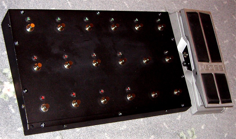
(the surface has since been blackened and labelled)
MIDI Foot Controller
Contents |
Overview |
^ top |
Here an overview of some features of my current MIDI foot controller (MFC). Also, read further below for ideas on how to build your own MFC!
(the surface has since been blackened and labelled)
About PCs, CCs and IAs |
^ top |
PCs and CCs are MIDI messages. IA is terminology used by some manufacturers to refer to a particular type of toggled CC message (see below).
PC = Program Change
Recalls a patch with its saved settings.
PCs have a number from 0 to 127, which commonly recalls patches labelled one higher, from 1 to 128.
CC = Continuous Controller
CC messages are capable of setting parameter values and can also be used to toggle effects on and off.
CC messages have a number and a value.
This is the equivalent of selecting a parameter with the number and setting that parameter to a value.
For example, CC number 7 is typically used for volume and sending values 0, 1, 2, 3, ... up to 127 would sweep the volume level from off to maximum.
CCs are numbered from 0 to 127 and most equipment manufacturers follow MIDI conventions where possible. The Fractal Axe-FX, however, has an open structure where nearly any CC number can be used for any available purpose. Note that CC numbers 0 and 32 are reserved for Bank changes sent before a PC message to allow access to more than 128 different patches. Never use these CC numbers as controllers, because following patch changes will be unpredictable.
CC values also range from 0 to 127 and are used in several different ways with MIDI foot controllers:
IA = Instant Access (or Immediate Access)
There is no such thing as an IA MIDI message.
IA is a term used by some manufacturers to refer to toggled CCs that switch effects on and off within a patch.
Turning effects off and on within a patch is often instantaneous, however, patch changes usually take some time to load, causing a brief sound dropout when sustaining notes while switching patches.
A Basic Project |
^ top |
Here's a schematic and code for a basic MIDI foot-controller. They have not been tested, no guarantees are given, no support is offered, and no responsibility is taken by GM Arts. Visit www.parallax.com for PBasic documentation and their editor, as well as help with Basic Stamp schematics. This is a cut-down version of my own design, and gives you:
Here's a list of what you'll need:
The schematic uses only 3 IC chips plus the stamp module. I used a BS2sx module, however, you're probably better off with the BS2p which is faster, pin compatible and has some additional commands and flexibility (eg you can can split code and data into separate memory areas). There's also a BS2p40 module which has 32 I/O pins instead of 16 - this could be handy if you want to control a large number of LEDs or relays, or perhaps to simplify input switching.
You could use an extra chip if you want to replace the diode footswitch encoder array with a 74C922 chip. I decided not to because the chip is more expensive and needs an extra stamp module pin for "a switch is pressed". The advantages of the chip are: you can detect 16 switches instead of 15, and the switch debouncing is done in hardware, not PBasic code.
A much cheaper and more powerful alternative to Basic Stamp is PicAxe. The extra power brings a little more complex coding, but there's not much in it. Porting Bacic Stamp to PicAxe is also quite easy.
Power is intended to be supplied via a 7-pin cable that also conforms to MIDI on pins 4 and 5. Expect to lose about 1V over a long cable, so taking this into account, you'll need about 10VDC @ 300mA, or 8VAC @ 400mA. The regulator should be placed on a heatsink.
PBasic code is shown below. This can be copied and pasted directly into the PBasic editor. It demonstrates how to program a Basic Stamp module to:
This example is coded for clarity, however, there are much better ways to do this that result in faster processing and room for more functionality. My own code, with all of the functionality described above and configuration data, uses about 25% of code space and 80% of RAM.
' {$STAMP BS2p}
' {$PBASIC 2.5}

'------------------------------------------------------------------------------------------------
' This is sample Basic Stamp code for a MIDI footcontroller
' It has not been tested, no guarantees are given, no support is offered and no responsibility is accepted
' It demonstrates how to use a Basic Stamp module to:
'  - use MIDI configuration data
'  - read & debounce footswitch presses
'  - send PC MIDI mesasages
'  - send CC toggle, momentary and tap messages
'  - display footswitch status LEDs
'  - read and autocalibrate a pedal controller and send continuous CC messages
' Adapted from a MIDI footcontroller built by GM Arts
'------------------------------------------------------------------------------------------------

'------------------------------------------------------------------------------------------------
' PBasic is similar to other versions of Basic, with some additional commands to support I/O
' on Basic Stamp modules.  The BS2p has enough code space, user RAM, pins and speed to support
' a fairly sophisticated foot controller.  The controller only sends MIDI data, it cannot receive
' MIDI data for 2-way communication with external devices.
'
' This program uses less than one third of EPROM code space in one of the 8 available slots,
' less than half of user RAM, no SP-RAM, and 13 of the 16 I/O pins (the BS2p40 offers 32 I/O pins!)
' see www.parallax.com for PBasic documentation, a PBasic editor, module information and schematics
'
' Some important gotchas:
'
' Never connect an output pin directly to +5V, earth or to the output of another device.  This can
' cause a short and destroy the module.  This project doesn't need any high current output pins,
' so for beginners, connect a 220 ohm resistor in series with every I/O pin to fully protect the chip.
' Even if pins start as inputs, several commands can automatically change a pin to an output.
'
' Take great care when using binary logic with IF statements.  PBasic allows several data types, but
' IF statements convert all variables to 16 bit.  eg if you have a bit variable IsPressed = 1 (true)
' you would expect "IF NOT IsPressed" to be false, but it actually returns a true result because the
' 1-bit variable is converted to 16 bits (0000000000000001) and "not IsPressed" = 1111111111111110
' which is also true.  One way to avoid this is to use XOR instead on NOT, so:  IF (tIsPressed ^ 1)
' is the same as 0000000000000001 XOR 0000000000000001 which = 0 (false), the desired result.

' PBasic calculates left to right within parenthesis first, then on the whole line, as integers
' eg 12 + 3 * 2 / 4   calculates as:   12+3 = 15,  15*2 = 30,   30/4 = 7 (integer math)

'------------------------------------------------------------------------------------------------

' This sample program has:
'   8 x PC footswitches (switches 1 to 8), each with a red LED
'   4 x CC toggle footswitches (switches 9 to 12), each with a green LED
'   2 x CC momentary footswitches (switches 13 & 14)
'   1 x CC tap footswitch (switch 15)
'   1 x CC pedal

'=====================================
' PINS
'=====================================

' The BS2p has 16 pins which can individually act as inputs or outputs

' fsw inputs are 1-based BCD on pins 0, 1, 2, 3 (high when pressed)

' 0-based PC data (0 to 7) is output as BCD on pins 4, 5, 6

' pin 7 is not used

' CC toggle LED states are output on these pins:
pinC9      PIN 8
pinC10     PIN 9
pinC11     PIN 10
pinC12     PIN 11

' pins 12 & 13 are not used

' pin 14 has associated circuitry to interface to a linear 10K pedal pot
pinPedalPot PIN 14 'used with RCTIME command

' pin 15 has current limiting resistor to connect to MIDI output
pinMidiOut  PIN 15

'=====================================
' I/O
'=====================================

' define inputs, outputs and startup states

  DIRA = %0000     'pins 0 to 3 are inputs for the 15 footswitches

  DIRB = %0111     'pins 4 to 6 are outputs (BCD for P fsw LED)
  OUTB = %0000     'all pins low (so P1 LED will be lit at startup)

  DIRH = %11001111 'pins 8 to 11, 14 & 15 are outputs (see pins above)
  OUTH = %01000000 'start pinPedalPot high in preparation for next RCTIME command

'=====================================
' USER CONFIG
'=====================================

MidiChan    CON 0     ' 0 to 15 for MIDI channel 1 to 16

' PC numbers for footswitches P1 to P8
P1num       CON 0
P2num       CON 1
P3num       CON 2
P4num       CON 3
P5num       CON 4
P6num       CON 5
P7num       CON 6
P8num       CON 7

' CC numbers below can be 1 to 31 or 33 to 127

' There are no real CC number standards for guitar effects, but here's what Line 6 use:
' CC1 Pedal 1/Tweak, CC2 Pedal 2, CC4 Wah Pedal, CC7 Volume Pedal, CC25 Stomp #1,
' CC26 Compressor/Booster, CC28 Delay, CC36 Reverb, CC43 Effect Pedal On*, CC50 Mod, CC63 EQ,
' CC64 Tap, CC69 Tuner, CC72 Pitch Shift, CC73 Double Tracker, CC105 Effect Pedal Off*,
' CC107 FX Loop, CC109 Stomp #2, CC110 Stomp #3, CC111 Amp #1, CC112 Amp #2, CC113 Tremolo
' * CC43 and CC105 work opposite when implemented (ie when CC43 is turned on,
' CC105 is turned off & vice versa) CC105 is typically used for a volume pedal

' CC numbers for toggle footswitches C9 to C12
C9num      CON 25   ' Stomp
C10num     CON 50   ' Mod
C11num     CON 28   ' Delay
C12num     CON 26   ' Boost

' Momentary footswitch CC numbers
M13num     CON 72   ' Pitch
M14num     CON 36   ' Reverb

' Tap footswitch CC number
T15num     CON 64   ' Tap

' Pedal CC number
PedCCnum   CON 7    ' Volume

'=====================================
' CONSTANTS
'=====================================

#SELECT $STAMP                    'set to 31.25 kBaud, open
  #CASE BS1
    #ERROR "BS1 is not supported"
  #CASE BS2, BS2E, BS2PE
    MidiBaud CON $8000 + 12
  #CASE BS2SX, BS2P
    MidiBaud CON $8000 + 60
  #CASE BS2PX
    MidiBaud CON $8000 + 108
#ENDSELECT

MidiPC        CON $C0 + MidiChan  'MIDI patch change command
MidiCC        CON $B0 + MidiChan  'MIDI continuous controller command

'switch debounce
fswTests      CON 3               'how many tests for the same fsw press result
fswPause      CON 2               'mSec to wait between footswitch tests

AbsoluteMax   CON 2000            'absolute max PedalValue to prevent overflows

'=====================================
' VARIABLES
'=====================================

nFswNow      VAR Nib   'fsw now result
nFswChange   VAR Nib   'which footswitches have changed

' RCTIME values - IMPORTANT - check results from your own schematic,
' and set Min and Max values to suit
' then check no calculations in the program overflow their data types !!!
wPedalValueNow  VAR Word 'starts as RCTIME value read from pedal
yLastPedalValue VAR Byte 'last pedal CC value sent

yPedalPotMin    VAR Byte
wPedalPotMax    VAR Word

'temp vars, initialised JIT before use
nTemp     VAR Nib
yData     VAR Byte

'=====================================
' INITIALISATION
'=====================================

  'RAM is set to zeros at powerup, so we can REM zero initialisations
  'nFswNow = 0
  'nFswChange = 0
  'wPedalValueNow = 0
  'yLastPedalValue = 0

  'RCTIME returns values of 70 - 1001 for 10K pot for RCTIME - series 1K & 0.1 cap - see schematic
  yPedalPotMin = 200                   'start with a conservative min (auto calibrates)
  wPedalPotMax = 500                   'start with a conservative max (auto calibrates)

'=====================================
' MAIN PROGRAM
'=====================================

  DO
    GOSUB GetSwitches
    GOSUB SendMidi
    GOSUB GetPedal
  LOOP

'=====================================
' SUBS
'=====================================

GetSwitches:

  'Footswitches P1 - P8, C9 - C12, M13 - M14 and T15 are high when pressed

  nFswChange = nFswNow ^ INA           'what's changed from last fsw press/release?
  IF nFswChange THEN                   'there is a change
    FOR nTemp = 2 TO fswTests          'check a few times
      PAUSE fswPause                   'wait a while
      IF nFswChange <> nFswNow ^ INA THEN
        nFswChange = 0                 'debounce test failed, so no change
        EXIT                           'exit for...next
      ENDIF
    NEXT
    nFswNow = nFswNow ^ nFswChange     'current fsw state
  ENDIF

RETURN

'=====================================================================================================

SendMidi:

  IF nFswChange   THEN  ' process switches if something's changed

    '------------------------------------------------------------------
    'handle tap data first (this is time-critical)
    IF nFswChange = 15 THEN       'Tap fsw changed

      IF nFswNow = 15 THEN    'Tap fsw pressed, send MIDI
        SEROUT pinMidiOut, MidiBaud, [MidiCC, T15num, $7F]
      ENDIF

    '------------------------------------------------------------------
    ELSEIF nFswChange <= 8 THEN 'this is a program change (fsw P1 to P8)

      yData = 255      'default invalid PC number

      SELECT nFswNow   'get pressed fsw (released P fsw's are ignored)
        CASE 1
          yData = P1num
        CASE 2
          yData = P2num
        CASE 3
          yData = P3num
        CASE 4
          yData = P4num
        CASE 5
          yData = P5num
        CASE 6
          yData = P6num
        CASE 7
          yData = P7num
        CASE 8
          yData = P8num
      ENDSELECT

      'send PC
      IF yData.BIT7 = 0 THEN  'a valid PC number has been set

        SEROUT pinMidiOut, MidiBaud, [MidiPC, yData]
        OUTB = nFswNow - 1   'display 0-based P footswitch output via pins 4, 5 & 6

        'you would include CC reset messages here

        'we'll just reset all C toggle LEDs to off
        '(so next C fsw press will turn a CC on)
        OUTC = %0000  'pins 8, 9, 10 & 11 set low

      ENDIF

    '------------------------------------------------------------------
    ELSEIF nFswChange >= 13 THEN 'this is a momentary switch M13 or M14 (T15 already handled above)

      SELECT nFswChange
        CASE 13
          yData = M13num
        CASE 14
          yData = M14num
      ENDSELECT

      IF nFswNow = nFswChange THEN  'momentary switch was pressed
          SEROUT pinMidiOut, MidiBaud, [MidiCC, yData, $7F]
      ELSE                          'momentary switch was released
          SEROUT pinMidiOut, MidiBaud, [MidiCC, yData, $00]
      ENDIF

    '------------------------------------------------------------------
    ELSE 'a CC toggle footswitch has changed C9 to C12

      yData = 255      'default invalid CC number

      SELECT nFswNow   'this ensures we're looking at a C fsw press, not a release

        CASE 9
          TOGGLE pinC9
          yData = C9num

        CASE 10
          TOGGLE pinC10
          yData = C10num

        CASE 11
          TOGGLE pinC11
          yData = C11num

        CASE 12
          TOGGLE pinC12
          yData = C12num

      ENDSELECT

      IF yData.BIT7 = 0 THEN  'a valid CC number has been set
        IF INS & (DCD (nFswChange - 1)) THEN  ' toggle LED is on
          SEROUT PINMidiOut, MidiBaud, [MidiCC, yData, $7F]
        ELSE 'toggle LED is off
          SEROUT pinMidiOut, MidiBaud, [MidiCC, yData, $00]
        ENDIF
      ENDIF

    ENDIF

  ENDIF

RETURN

'=====================================================================================================

GetPedal:

  'read pedal value, auto-calibrate min and max as required

  'read pedal pot
  RCTIME pinPedalPot, 1, wPedalValueNow
  HIGH pinPedalPot  'for next time

  'recalibrate pedal range?
  IF wPedalValueNow < yPedalPotMin THEN
    'PedalValue = 0 if RCTIME reaches max time (136mS on BS2?)
    'this happens if pedal is open circuit, so ignore this case
    'PedalValue = 1 if some fault prevents timed measurement
    IF wPedalValueNow > 1 THEN
      yPedalPotMin = wPedalValueNow
    ELSE
      wPedalValueNow = yPedalPotMin
    ENDIF

  ELSEIF wPedalValueNow > wPedalPotMax THEN
    'must limit max to prevent calc overflow below
    'ignore really high values (pedal is probably high resistance)
    IF wPedalValueNow <= AbsoluteMax THEN
      wPedalPotMax = wPedalValueNow
    ELSE
      wPedalValueNow = wPedalPotMax
    ENDIF
  ENDIF

  'adjust to range
  wPedalValueNow = wPedalValueNow - yPedalPotMin    'zero based, 0 to (max - min)

  'scale to MIDI data range (0 to 127)
  'in this calc, AbsoluteMax value = 2000, / 4 = 500, * 127 = 63500 (ok, doesn't exceed 65535) ... etc
  wPedalValueNow = ((wPedalValueNow >> 2) * 127) / ((wPedalPotMax - yPedalPotMin) >> 2)

  'don't re-send if same as last value
  IF wPedalValueNow <> yLastPedalValue THEN
    yLastPedalValue = wPedalValueNow.BYTE0
    SEROUT pinMidiOut, MidiBaud, [MidiCC, PedCCnum, yLastPedalValue]
  ENDIF

RETURN

'=====================================================================================================
'end of code
|